












Content
Direct Answer and Scope Boundary
The deployment of hotel guest-room minibars requires a framework governing equipment specification, installation parameters, service-space requirements, and replenishment handover controls. This guide provides procurement, design coordination, engineering, and rooms operations teams with matrices and checklists to execute this specific scope. To maintain operational boundaries, this document focuses exclusively on the guest-room minibar unit and its immediate physical interfaces within the designated cabinet enclosure. For broader project scopes, readers should consult the hotel opening equipment checklist, the hotel FF&E and OS&E classification guide, and the hotel fixed furniture procurement workflow. This guide excludes beverage strategy, revenue advice, amenity selection, energy efficiency, noise ratings, cooling performance, cost savings, food-safety outcomes, and jurisdiction-specific compliance; it is a technical procurement and handover control document designed to structure the buyer's documentation file.
Equipment Specification Matrix
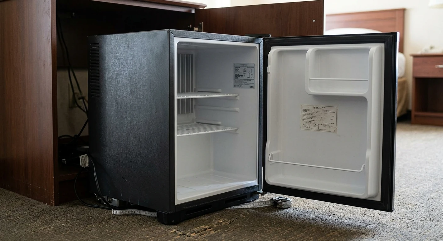
The foundation of a minibar deployment is a detailed equipment specification matrix. Procurement teams compile this matrix by populating fields with data provided by the selected manufacturer for the specific model being purchased. This matrix serves as the central reference for subsequent design coordination, engineering reviews, and operational planning. Buyers extract exterior dimensions, internal volume, and hardware configurations directly from the supplier's technical data sheets to ensure the procurement file reflects the exact physical asset.
When defining the electrical and safety standards for the specification, buyers request documentation appropriate for the intended use environment. For example, the IEC 60335-2-24:2020 Scope Page explicitly includes refrigerating appliances used by clients in hotels and distinguishes them from commercial refrigerating appliances covered elsewhere. Buyers use this published scope definition to request the applicable standards declaration for the exact product and destination market from the supplier. This document does not claim product certification, project approval, or jurisdictional compliance; it instructs the buyer on how to request the correct documentation for their specific procurement file. The supplier's declaration is then archived alongside the purchase order.
The following matrix is completed by the procurement team based on project-specific timelines. Fields require inputs from the manufacturer's official documentation.
| Specification Category | Required Buyer-Entered Field | Documentation Source and Verification Requirement |
|---|---|---|
| Equipment Identification | Exact Manufacturer and Model Number | Matches the manufacturer's official catalog and the final purchase order. Generic terms are replaced with exact model numbers. |
| Physical Dimensions | Height, Width, Depth (Exterior) | Extracted directly from the selected model's technical data sheet. Used to dictate case-good internal clearances and physical fit. |
| Internal Capacity | Total Volume (Liters) | Recorded from the manufacturer's specification. Used by operations to plan par counts and physical stock positions. |
| Electrical Requirements | Voltage and Frequency | Matches the destination property's electrical grid. Verified against the manufacturer's technical specifications and submittals. |
| Refrigeration Technology | Cooling System Type | Buyer specifies the exact technology (e.g., absorption, thermoelectric, compressor) as defined by the manufacturer's documentation. |
| Hardware and Finishes | Door Type, Hinge Position, Lock Type, Exterior Finish | Coordinated with the interior design package. Specifies if hinges are reversible or fixed, and if locks are mechanical or electronic. |
| Compliance and Identification | Rating Plate Location and Details | Buyer documents where the rating plate is located on the unit for future engineering asset tracking and physical verification. |
| Documentation | Installation Manuals, Operating Manuals | Supplier provides exact manuals for the specified model. Generic manuals are subject to submittal review and replacement. |
| Support and Coverage | Warranty Terms and Authorized Service Contact | Buyer records the exact warranty duration, inclusions, exclusions, and the local authorized service agent's contact details. |
Case-Good Interface Checklist
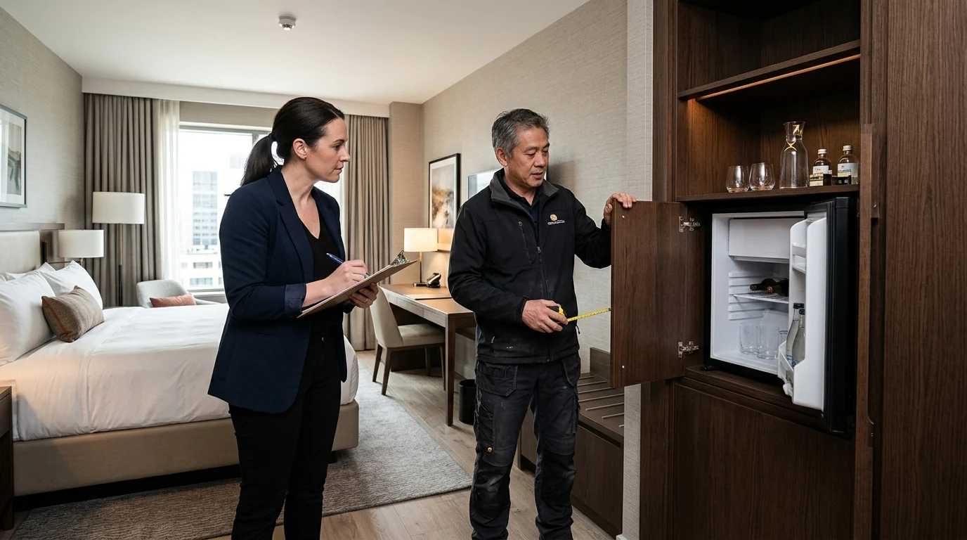
The integration of a minibar into a guest-room case-good is a coordination point that requires alignment between the equipment and the surrounding furniture. Coordination of the physical interface involves verifying that the cabinet enclosure accommodates the minibar's dimensions, ventilation requirements, and door operation. Dimensions, clearances, openings, and fixing values utilized in the design and construction of the case-good are sourced directly from the selected model manual and the approved shop drawing. Procurement and design coordination teams avoid applying universal clearances, instead relying on the specific requirements published by the manufacturer for the purchased unit.
To illustrate the necessity of model-specific coordination, consider the Minibar Systems SmartCube Case-Good Ventilation Specification. This case-good document shows model-specific inlet/exhaust, free-space discharge, mounting, and anti-tilt coordination details. It serves as an example of why buyers support a drawing-review and installation-handover control for case-good interfaces based on the exact model selected. Similarly, the Dometic DM50CD/DM50CF Installation and Operating Manual provides its own recess, ventilation-opening, rear-clearance, fastening, electrical-connection, and door-decor requirements. Procurement teams require this level of model-specific cabinet and installation evidence in the specification and submittal review, without generalizing its measurements to another model. The case-good shop drawings are cross-referenced against these manuals to verify that the physical enclosure supports the equipment's operational parameters.
The following checklist is utilized by the design coordination and engineering teams to verify that the case-good shop drawings align with the minibar manufacturer's requirements.
| Interface Coordination Point | Verification Requirement (Sourced from Exact Model Manual) | Responsible Party for Sign-Off |
|---|---|---|
| Internal Cabinet Dimensions | Verify that the internal height, width, and depth of the case-good meet the minimum clearances specified in the selected minibar manual. | Design Coordination / Case-Good Contractor |
| Inlet Ventilation Opening | Confirm the square area and location of the air inlet (typically at the base) matches the model-specific manual requirements. | Engineering / Case-Good Contractor |
| Exhaust Ventilation Opening | Confirm the square area and location of the air exhaust (typically at the top or rear) matches the model-specific manual requirements. | Engineering / Case-Good Contractor |
| Free-Space Discharge Path | Verify that the internal cabinet design allows for an unobstructed airflow path from the inlet, across the cooling unit, to the exhaust as specified. | Engineering / Design Coordination |
| Power Cord Routing | Ensure the case-good includes a specifically sized and located opening to route the minibar power cord to the designated electrical socket. | Engineering / Case-Good Contractor |
| Mounting and Anti-Tilt Fixing | Confirm the case-good base and side walls are constructed to accept the mounting screws and anti-tilt brackets specified in the minibar manual. | Case-Good Contractor / Installer |
| Door Hinge and Slide Coordination | If utilizing a sliding hinge mechanism to connect the cabinet door to the minibar door, verify the offset and clearance requirements from the manual. | Design Coordination / Installer |
| Decor Panel Integration | If the minibar accepts a custom decor panel, verify the maximum thickness, weight, and dimensions permitted by the manufacturer's manual. | Design Coordination / Case-Good Contractor |
Installation and Service-Space Checklist
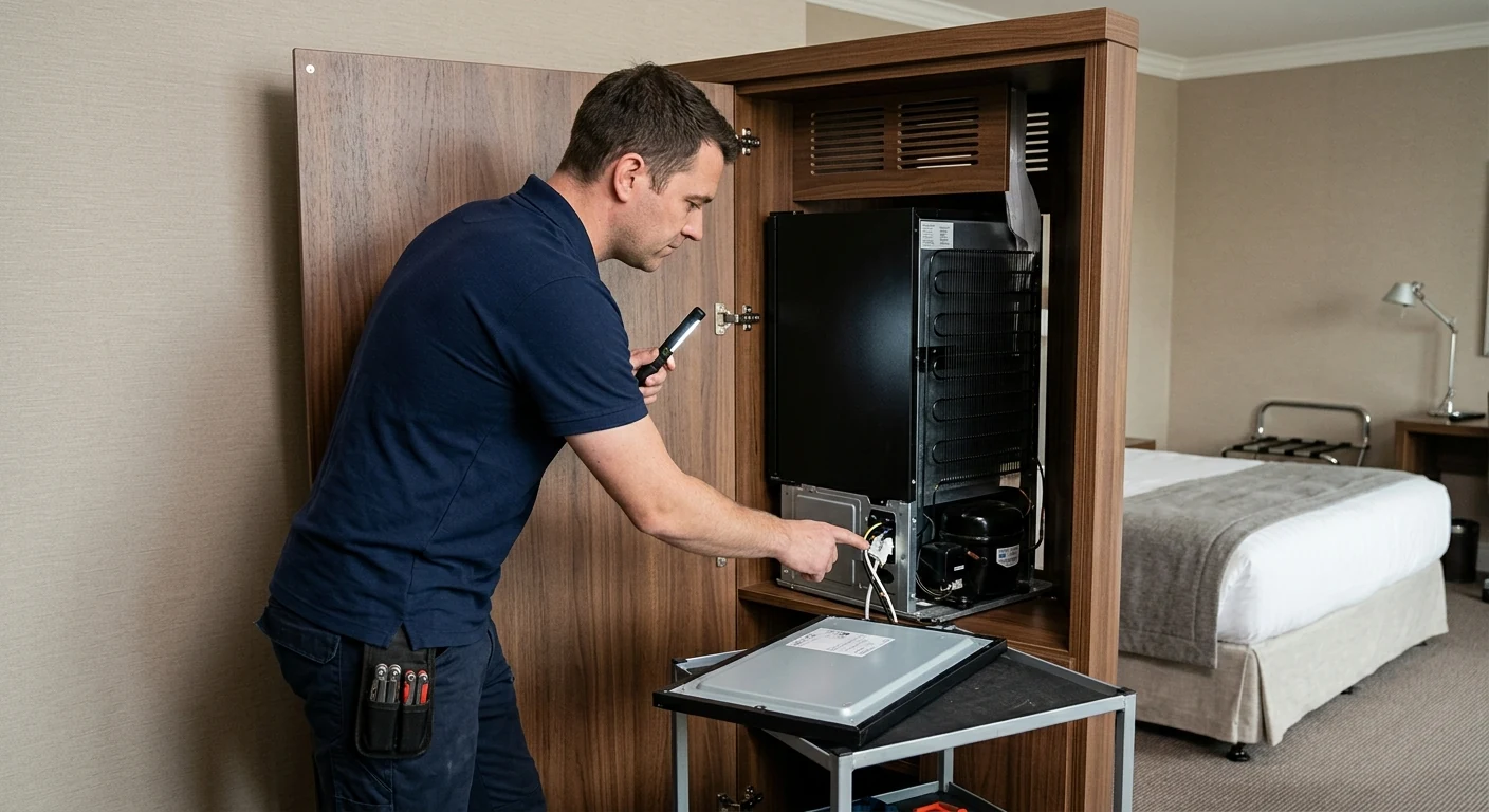
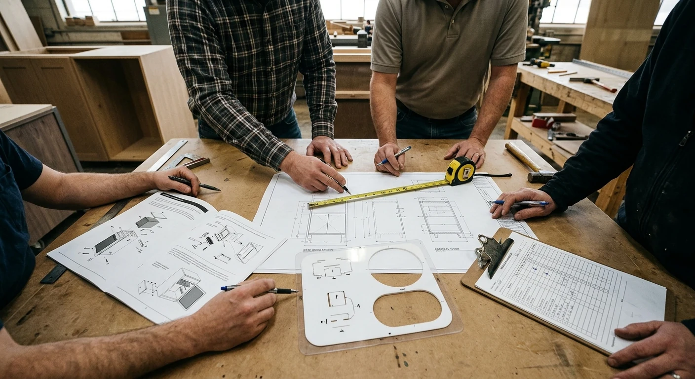
Once the case-good is constructed and approved, the physical installation of the minibar is executed according to the manufacturer's guidelines. The installation process involves verifying ventilation paths, leveling the unit, securing the hardware, and confirming that service and maintenance access is preserved for the engineering team. Numerical installation values and procedural steps are attributed to the exact manual of the purchased model. Installers reference the manual to determine the correct placement of anti-tilt brackets, the routing of the power cord, and the adjustment of the door hinges.
For example, the Minibar Systems Primo LVD Installation Manual provides product-specific rating-plate, ventilation, level, fixing, heat-source, power-cord, and door-slide checks. Procurement and engineering teams build a supplier-submittal checklist that records these exact requirements rather than adopting them universally. Furthermore, long-term maintenance is considered during installation. The Dometic RH Series Installation and Operating Manual identifies ventilation, fixing, cleaning, condensate-drain, vent-cleaning, and troubleshooting checks for the named RH models. Buyers define the service-space and maintenance-document handover fields based on the exact supplier manual without inventing intervals or universal claims. The engineering team verifies that the installed unit allows for the removal of access panels and the cleaning of condensate trays as specified by the manufacturer.
The following checklist governs the physical installation and the verification of service-space requirements. It is completed by the installer and verified by the engineering team based on project-specific workflows.
| Installation and Service Check | Execution and Verification Standard (Per Exact Model Manual) | Verification Owner |
|---|---|---|
| Ventilation Path Confirmation | Physically verify that the installed unit does not block the case-good inlet or exhaust openings and that the required rear clearance is maintained. | Engineering / Installer |
| Power Cord and Socket Access | Confirm the power cord is routed without tension or pinching, and that the electrical socket remains accessible for disconnection. | Engineering |
| Leveling and Alignment | Verify the unit is leveled using the adjustable feet (if equipped) as specified in the manual to support door sealing and operation. | Installer / Engineering |
| Fixing and Anti-Tilt Securing | Confirm all required mounting screws and anti-tilt brackets are installed as detailed in the manufacturer's installation manual. | Installer |
| Door Swing and Seal Check | Verify the door opens to the required angle without binding against the case-good, and that the magnetic seal engages upon closing. | Installer / Operations |
| Removable Panel Access | Ensure that any removable panels required for maintenance (e.g., accessing the cooling unit or control board) can be removed as specified. | Engineering |
| Condensate and Cleaning Access | Verify that the condensate drain (if applicable) and interior surfaces can be accessed for routine cleaning as specified in the maintenance manual. | Engineering / Operations |
| Asset-Tag Visibility | Confirm that the property's fixed asset tag and the manufacturer's rating plate are visible or accessible based on the approved submittal. | Procurement / Engineering |
Sample-Room and Submittal Sign-Off
Before mass installation commences, a mock-up is executed in a designated sample room. This sample room serves as a physical reference, ensuring that the procurement specification, the case-good design, and the installation procedures align. The sample-room sign-off is a project-specific milestone in the procurement and deployment workflow. Deliveries and installations proceed after relevant stakeholders review the physical installation and sign off on their respective areas of responsibility based on the contract terms.
The submittal and sample-room review process requires coordination among multiple departments. The procurement team verifies that the physical unit matches the approved specification matrix, checking the model number, finishes, and delivered documentation against the purchase order. The design coordination team verifies the aesthetic integration and case-good fit, ensuring that decor panels and sliding hinges operate as intended. The engineering team verifies the electrical connections, ventilation clearances, and service access, confirming that the power cord is routed without tension and that the socket remains accessible. The installer demonstrates that the fixing and leveling procedures from the manual have been followed. Finally, the rooms operations team verifies that the unit can be accessed, restocked, and cleaned according to their operational parameters.
The following sign-off matrix is completed and archived as part of the formal project handover documentation.
| Stakeholder / Department | Specific Verification Responsibility in Sample Room | Sign-Off Status (Approved / Rejected / Conditional) |
|---|---|---|
| Procurement Team | Verifies the manufacturer, model number, finishes, and delivered documentation match the approved purchase order and specification matrix. | [Buyer to Complete] |
| Design Coordination / Case-Good | Verifies the physical fit within the cabinet, the alignment of decor panels, the operation of sliding hinges, and aesthetic integration. | [Buyer to Complete] |
| Engineering Team | Verifies electrical socket location, power cord routing, ventilation clearances, leveling, fixing, and access for future maintenance. | [Buyer to Complete] |
| Installation Contractor | Demonstrates that physical installation steps, including anti-tilt securing and door alignment, comply with the model-specific manual. | [Buyer to Complete] |
| Rooms Operations Team | Verifies the ergonomics of opening the door, accessing the interior for restocking, operating the lock (if applicable), and cleaning access. | [Buyer to Complete] |
Replenishment Handover Matrix
The final phase of the minibar deployment is the handover to the rooms operations team for management and replenishment. This phase utilizes an operational control matrix to standardize the physical act of restocking. This guide explicitly excludes any advice on beverage strategy, menu selection, pricing, revenue management, or amenity curation. The focus here is solely on the physical logistics of the replenishment process, the management of par counts, and the control of physical access based on the equipment's internal volume and hardware configuration.
The replenishment handover matrix establishes the baseline operational parameters that the buyer supplies. It defines how many items fit in the unit, where they are positioned on the shelves or door racks, how the restocking cart navigates from the service elevator to the room, and how discrepancies or physical damages are escalated to the engineering team. By standardizing these physical controls, the operations team executes tasks based on buyer-defined frequencies without ambiguity regarding the equipment's capacity or access protocols. The matrix is tailored to the specific model's interior layout, ensuring that the physical stock position planogram aligns with the available shelf space.
The following matrix is populated by the rooms operations management team based on project-specific schedules. Fields require specific, actionable data supplied by the buyer.
| Replenishment Control Field | Buyer-Supplied Operational Parameter | Owner and Frequency |
|---|---|---|
| Par Count Fields | Define the maximum physical quantity of each item category (e.g., bottles, cans, snacks) that the specific minibar model can hold based on its internal volume. | Rooms Operations / Buyer-defined frequency |
| Stock Position Planogram | Provide a physical layout diagram indicating which shelf or door rack holds which item, supporting consistent presentation and counting. | Rooms Operations / Buyer-defined frequency |
| Refill Route and Logistics | Document the approved physical route for the restocking cart from the service elevator to the guest rooms, including cart storage locations. | Rooms Operations / Buyer-defined frequency |
| Count Sheet Integration | Confirm that the physical par counts align with the printed or digital count sheets used by the attendants during the room service. | Rooms Operations / Buyer-defined frequency |
| Discrepancy Escalation Protocol | Define the reporting chain if an attendant discovers physical damage to the minibar, a broken shelf, a failed light, or a blocked ventilation grille. | Rooms Operations to Engineering / As required |
| Keys and Locks Management | If the minibar features a mechanical lock, define the key control log, sign-out procedure for attendants, and the protocol for lost keys. | Security and Rooms Operations / Buyer-defined frequency |
Exception Log and Final Acceptance Workflow
During the installation phase, deviations and exceptions may occur due to variations in room construction, discrepancies in case-good manufacturing, or physical damage during transit. To manage installations that do not match the approved standard, a formal exception log and final acceptance workflow are implemented based on contract-specific terms.
The exception log is a tracking tool that documents non-compliant installations. If an installer or engineer identifies a unit where the ventilation clearance cannot be met, where the power cord is pinched, or where the door binds against the cabinet, the issue is documented in the log. The log records the specific room number, the nature of the deviation from the manufacturer's manual, the responsible party for remediation, and the required corrective action. Rooms are handed over to operations after exceptions for that specific room are resolved and signed off by the engineering team according to the project schedule.
The final acceptance workflow involves a physical inspection of the installed units. The engineering team utilizes the Installation and Service-Space Checklist to verify compliance with the manufacturer's manual and the approved shop drawings. When a room passes this inspection, the minibar is handed over from the project phase to the operational phase.
The following table outlines the data entry requirements for the exception log.
| Exception Tracking Field | Description of Required Data Entry | Workflow Action and Responsibility |
|---|---|---|
| Room Number and Location | Identification of the guest room and specific case-good location where the deviation was identified. | Logged by Installer or Inspector upon discovery. |
| Description of Deviation | Detail of how the installation fails to meet the requirements of the manufacturer's manual or approved shop drawing. | Documented with photographs and reference to the specific manual page. |
| Responsible Party for Remediation | Identification of the contractor or department required to fix the issue (e.g., Case-Good Contractor for cabinet adjustments, Installer for leveling). | Assigned by the Project Manager or Design Coordinator. |
| Corrective Action Required | The specific physical steps required to bring the installation into compliance with the specification and manual. | Defined by Engineering in consultation with the manufacturer's guidelines. |
| Re-Inspection and Final Sign-Off | The date and signature of the engineering representative confirming that the corrective action has been completed. | Verification step before the room is released to operations based on contract terms. |
RFQ and Handover Record Checklist
To finalize the procurement file, buyers compile the following deliverables into the project handover record. For further support, procurement teams can request a minibar specification and handover review.
Supplier-provided technical data sheet detailing model-specific exterior dimensions, internal volume, and hardware configurations.
Manufacturer's installation manual specifying ventilation clearances, power cord routing, leveling procedures, and fixing requirements.
Approved case-good shop drawings demonstrating physical integration, free-space discharge paths, and decor panel compatibility with the selected minibar model.
Applicable standards declarations requested for the exact product and destination market, referencing published scopes such as IEC 60335-2-24.
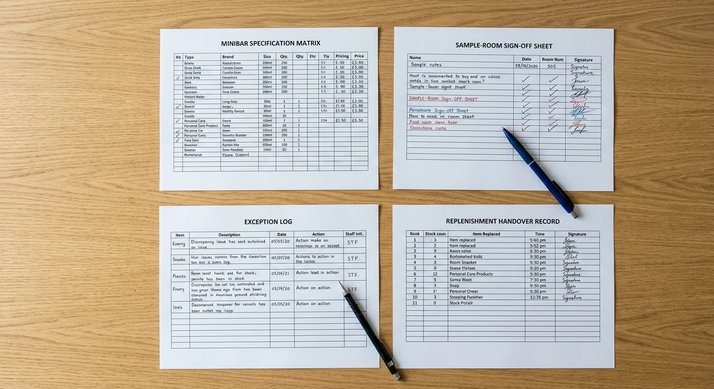
Completed sample-room sign-off matrix recording design coordination, engineering verification, and operations approvals based on the physical mock-up.
Buyer-defined replenishment handover matrix detailing model-specific par counts, physical stock position planograms, and access protocols.
Frequently Asked Questions
How is model substitution handled after case-good shop drawings are approved?
If a minibar model is substituted after case-good approval, the buyer initiates a revised submittal review. The new model's specific dimensions, ventilation requirements, and fixing points are cross-referenced against the existing cabinet design. The case-good contractor and engineering team review the updated manufacturer manual to determine if cabinet modifications are required before proceeding with the revised purchase order.
Who signs off on ventilation and service access during the sample-room review?
The engineering team or the designated project mechanical consultant signs off on ventilation and service access. This verification confirms that the physical installation aligns with the clearances, airflow paths, and maintenance access points specified in the selected manufacturer's installation manual.
What specific data goes into the replenishment handover matrix?
The replenishment handover matrix contains buyer-defined operational parameters, including model-specific par counts, physical stock position planograms, restocking cart logistics, count sheet integration details, discrepancy escalation protocols, and key management procedures for mechanical locks.
How are installation deviations recorded and resolved?
Installation deviations are recorded in a project-specific exception log. The log documents the location, the nature of the deviation from the manufacturer's manual or approved drawing, the party responsible for remediation, and the required corrective action. The engineering team verifies the resolution based on contract-specific acceptance workflows.
Get the week's latest industry information
-
Real-Life Professional Restaurant Case Studies
Explore Now
-
Create a unique restaurant with over 95,700+products
Explore Now
-
Protessional Free 3D Restaurant Design
Explore Now
-
Still Have Questions About Opening a Restaurant?
Explore Now

Sylvia
With 8 years in catering & hospitality industry, sales manager of Ron Group, specialise in providing one stop solutions to restaurants, hotels and weddings.
Discover Our Exclusive Products
Explore our extensive range of restaurant and hotel supplies designed to enhance your operations. Find the perfect solutions to meet your needs.
Browse Our ProductsFREE 3D DESIGN
Boost your restaurant's success with our free 3D design service. Start building the restaurant of your dreams today!
Explore 3D Design Case
RECOMMENDED CASES
-

La Rambla by Catalunya: Crafting Barcelona's Soul in Hong Kong - Custom Furniture Excellence
RON Group's custom Spanish-inspired furniture elevates La Rambla with artisanal aesthetics...
Learn More -

Cardinal Point: Elevating Outdoor Seating with Tailored Cushion Upgrades
Discover how Cardinal Point transformed its outdoor dining experience with custom cushions, achievin
Learn More
RECOMMENDED BLOGS
-

Bar Glassware 101: Types, Names, Uses, and How to Stock Your Bar
Learn the 10 core bar glassware types, names, and uses. Discover how to stock your bar with the right glasses for cocktails, beer,...
Sylvia2026-07-26 -

Complete Bar Equipment List for Opening a Bar
Use a complete bar equipment list with pictures, covering workstations, ice, refrigeration, glassware, utilities, sanitation and a...
Sylvia2026-06-11 -

Low-Budget Restaurant Interior Design Ideas: Spend Where Guests and Staff Notice
Explore low-budget restaurant interior design ideas, practical material choices, layout priorities and phased upgrades without...
Sylvia2026-04-04
Subscribe to RON GROUP
Stay up-to-date with the latest industry insights and expert advice. Together, we'll create your ideal restaurant.